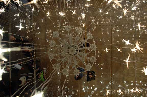
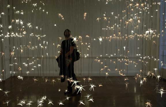
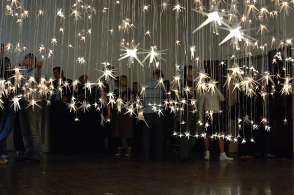
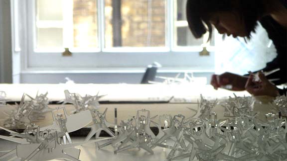
marc fornes & theverymany have been invited by Alex Haw (from Atmos and AA Ddiploma Master Unit 13) to collaborate to "LightHive : luminous architectural surveillance", an installation for the Architectural Association, London, April 2007.
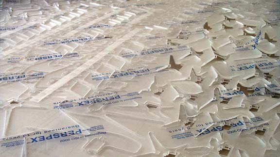
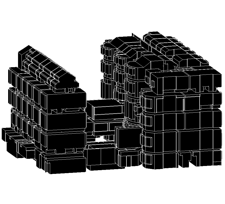
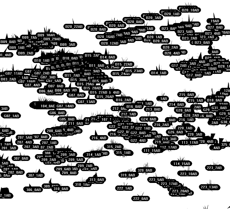
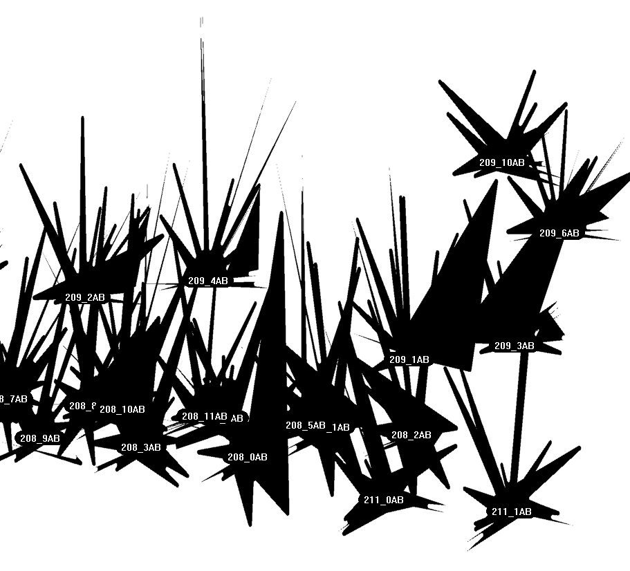
EXPLICIT PROTOCOL v1.0: for every room of the 3d model of Architectural Association Building (including symbolic furniture) create Longitudinal and transversal section through the location of each light source, generate from the intersection boundaries a LED diffuser shape (each as a set of two planar shapes intersecting at 90 degrees), anotate the components and finally unfold them (to be laser-cut into flat acrylic sheets)...
According to the amount of components (more than 1400!), the challenge of that project is to build up the rhino engine code as light as possible in order to be abble to run it in one go! the entire descriptive process is yet taking 25 seconds to generate around 1200 components...
In progress...

BOUNDARY REPRESENTATION / BREPS (ie Wikipedia)
In computer-aided design, boundary representation—often abbreviated as B-rep or BREP—is a method for representing shapes using the limits. A solid is represented as a collection of connected surface elements, the boundary between solid and non-solid. The basic method was developed independently in the early 1970s by Braid in Cambridge (for CAD) and Baumgart in America (for computer vision). Braid continued his work with the research solid modeller BUILD which was the forerunner of many research and commercial solid modelling systems. Braid worked on the commercial systems ROMULUS, the forerunner of Parasolid, and on ACIS. Parasolid and ACIS are the basis for many of today's commercial CAD systems.
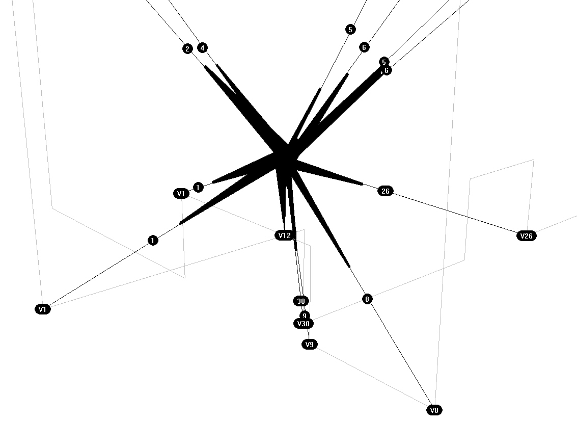
Boundary representation models are comprised of two parts: topology and geometry. The main topological items are: faces, edges and vertices. A face is a bounded portion of a surface; an edge is a bounded piece of a curve and a vertex lies at a point. Other elements are the shell (a set of connected faces), the loop (a circuit of edges bounding a face) and loop-edge links (also known as winged-edge links or half-edges) which are used to create the edge circuits.
Unlike the constructive solid geometry (CSG) representation, which represents objects as a collection of primitive objects and Boolean operations to combine them, boundary representation is more flexible and has a much richer operation set. This richer operation set makes boundary representation a more appropriate choice for CAD systems than CSG. CSG was used initially by several commercial systems because it was easier to implement but the advent of reliable commercial B-rep kernel systems like Parasolid and ACIS, mentioned above, has led to widespread adoption of B-rep for CAD. As well as the Boolean operations, B-rep has extrusion, chamfering, blending, drafting, shelling, tweaking and other operations which make use of these.
Boundary representation is essentially a local representation connecting faces, edges and vertices. An extension of this was to group sub-elements of the shape into logical units called "features". Pioneering work was done on this by Kyprianou in Cambridge using the BUILD system and continued and extended by Jared and others. Much other work on this topic has been done in several research centres throughout the world and it is a subject of continuing interest. Features, or geometric features, are the basis of many other developments, allowing high-level "geometric reasoning" about shape for comparison, process-planning, manufacturing, etc.
Boundary representation has also been extended to allow special, non-solid model types called non-manifold models. As described by Braid, normal solids found in nature have the property that, at every point on the boundary, a small enough sphere around the point is divided into two pieces, one inside and one outside the object. Non-manifold models break this rule. An important sub-class of non-manifold models are sheet objects which are used to represent thin-plate objects and integrate surface modelling into a solid modelling environment.
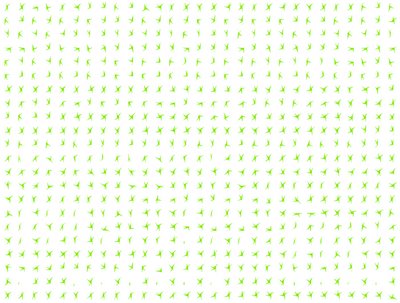
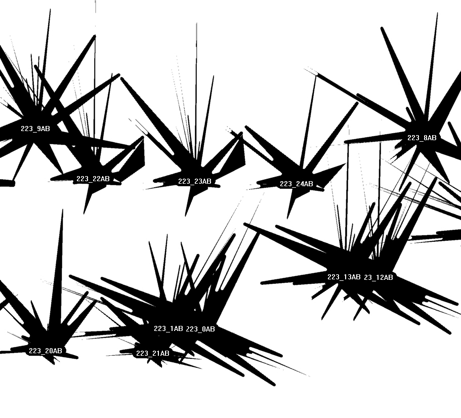
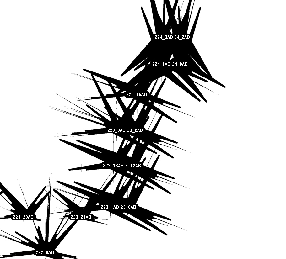
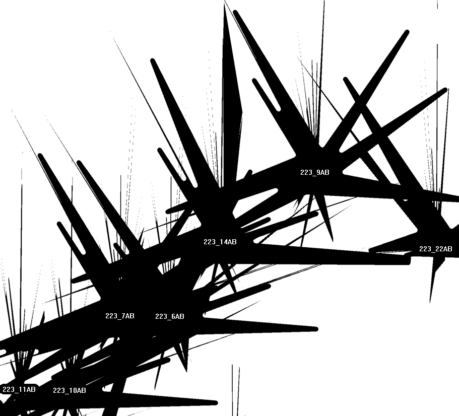
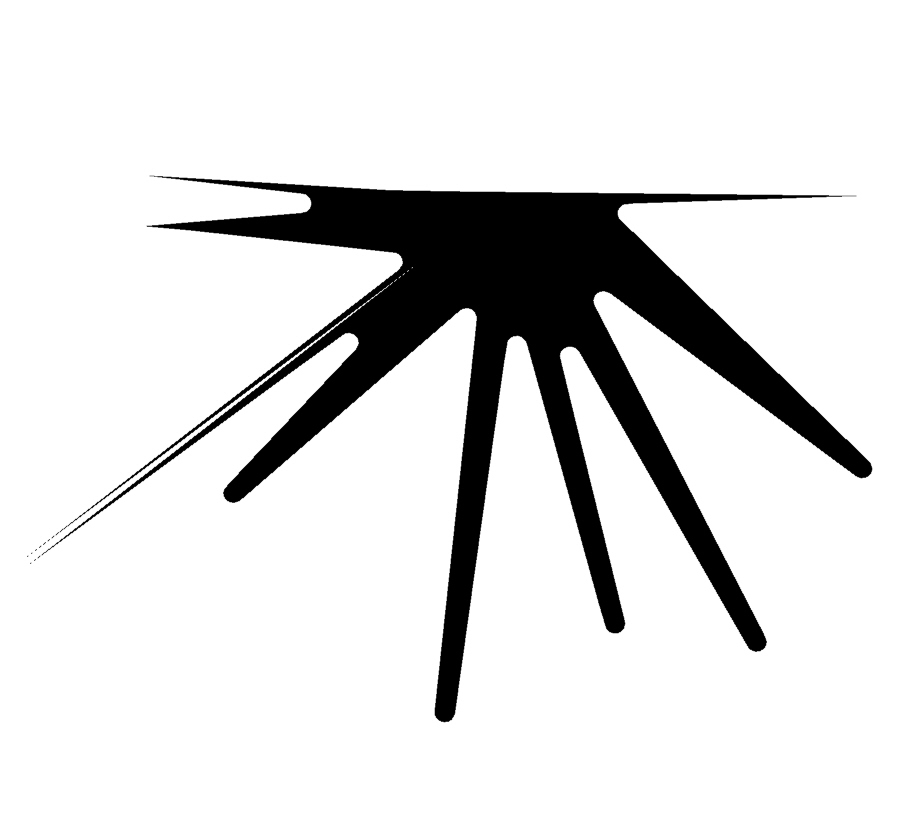
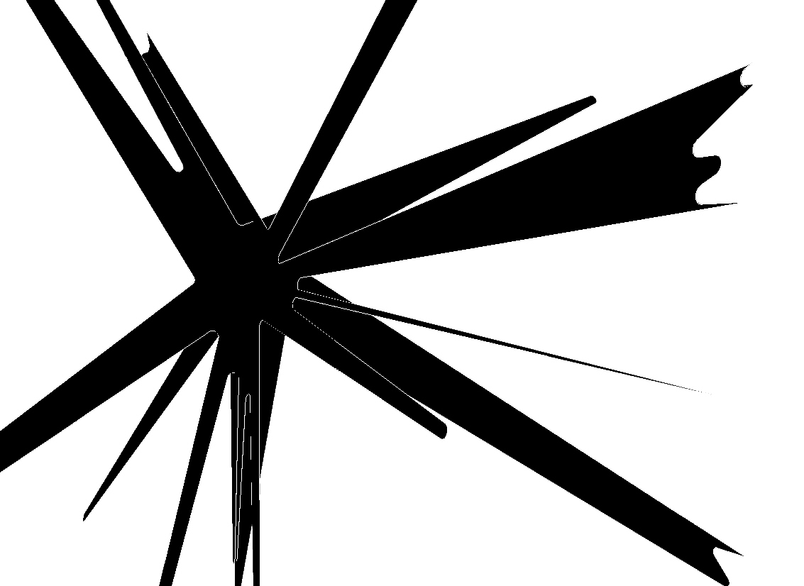
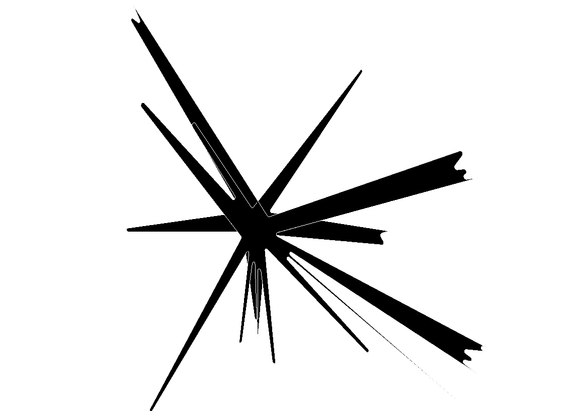
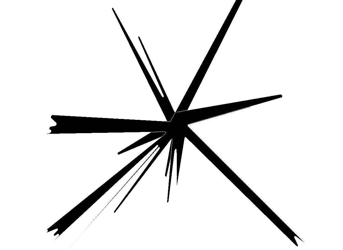
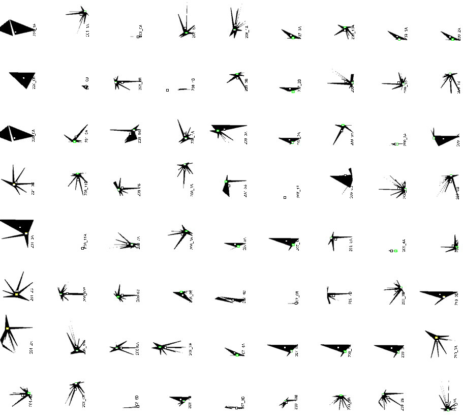
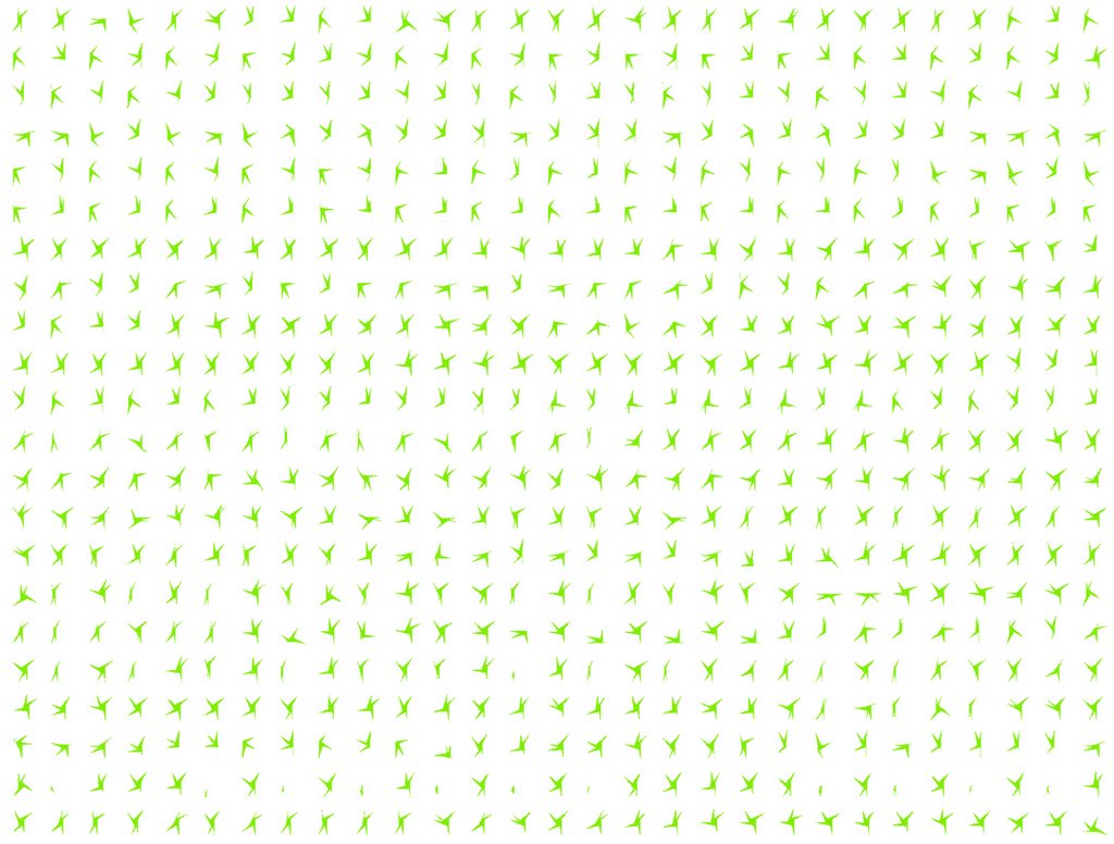
1200 components flat, all similar but all different
Tips'n tricks: (part of code only)
' getBoundingBox
arrBoundingBox = Rhino.BoundingBox(arrPolySrfs(i))
dblPlaneHeight = rhino.distance(arrBoundingBox(0), arrBoundingBox(4))
dblPlaneLong = rhino.distance(arrBoundingBox(0), arrBoundingBox(1))
dblPlaneTrans = rhino.distance(arrBoundingBox(0), arrBoundingBox(3))
' cuttingPlane LONGITUDINAL
arrPlaneOriginLong = array(arrPt(0)-dblPlaneLong, arrPt(1), arrPt(2)-dblPlaneHeight)
arrPlaneLong = Rhino.MovePlane (Rhino.WorldZXPlane, arrPlaneOriginLong)
strPlaneSrfLong = Rhino.AddPlaneSurface (arrPlaneLong, 2*dblPlaneHeight, 2*dblPlaneLong)
' intersect
strCrvIntersect = Rhino.IntersectBreps (arrPolySrfs(i), strPlaneSrfLong)
strCrvIntersectJoin = Rhino.JoinCurves (strCrvIntersect, True)
Call Rhino.SimplifyCurve (strCrvIntersect)
arrVertices = Rhino.CurveEditPoints(strCrvIntersect)
Labels: AA, Alex Haw, Architectural Association, Boundary representation, Breps, LightHive