Monday, November 26, 2007

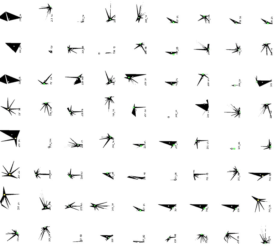
071117_Aperiodic_Series003_Gazebo


PAVILION - Free-standing structure (ie wikipedia)
Pavilion may refer to a free-standing structure sited a short distance from a main residence, whose architecture makes it an object of pleasure. Large or small, there is usually a connection with relaxation and pleasure in its intended use. A pavilion built to take advantage of a view is referred to as a gazebo.


POWERS OF TEN (ie wikipedia)
Powers of Ten is a 1977 short documentary film written and directed by Charles Eames and his wife, Ray. The film depicts the relative scale of the Universe in factors of ten (see also logarithmic scale and order of magnitude). The film is a modern adaptation of the 1957 book Cosmic View by Kees Boeke---and more recently is the basis of a new book version. Both adaptations, film and book, follow the the form of the Boeke original, adding color and photography to the black and white drawings employed by Boeke in his seminal work (Boeke's original concept and visual treatment is all too often uncredited or insufficiently credited in contemporary accounts).

The film begins with an aerial image of a man reclining on a blanket; the view is that of one metre across. The viewpoint, accompanied by expository voiceover by Philip Morrison, then slowly zooms out to a view ten metres across ( or 101 m in standard form), revealing that the man is picnicking in a park with a female companion. The zoom-out continues, to a view of 100 metres (10² m), then 1 kilometre (10³ m), and so on, increasing the perspective—the picnic is revealed to be taking place near Soldier Field on Chicago's lakefront—and continuing to zoom out to a field of view of 1024 metres, or the size of the observable universe. The camera then zooms back in to the picnic, and then to views of negative powers of ten—10-1 m (10 centimetres), and so forth, until we are viewing a carbon nucleus inside the man's hand at a range of 10-18 metre.


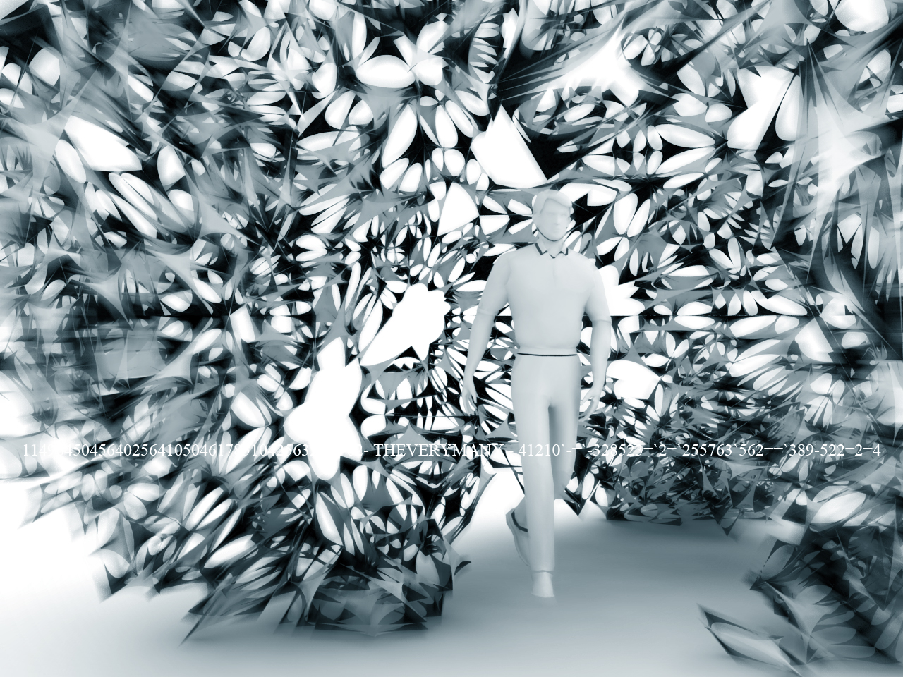
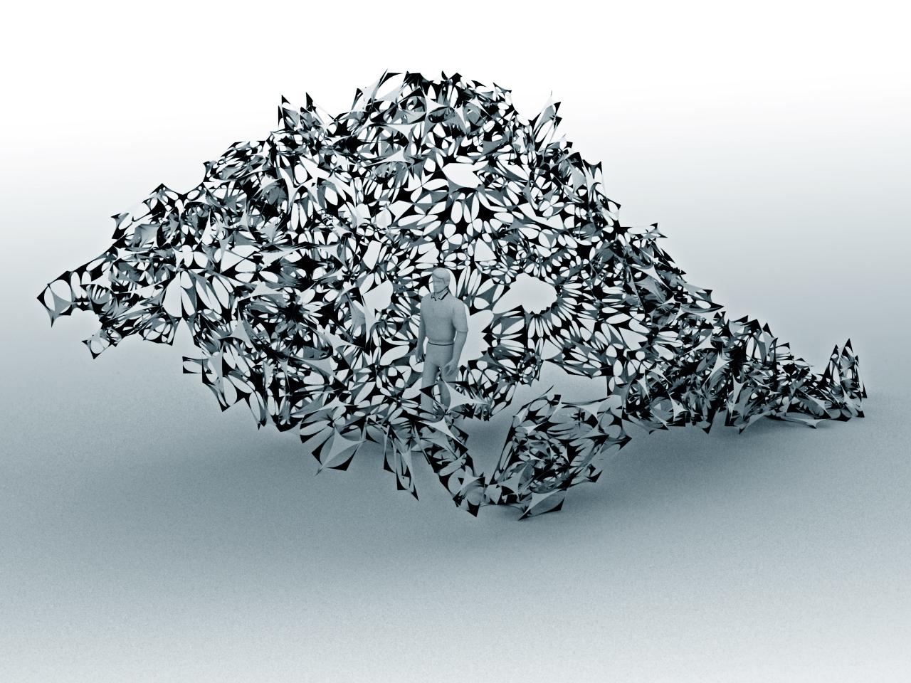
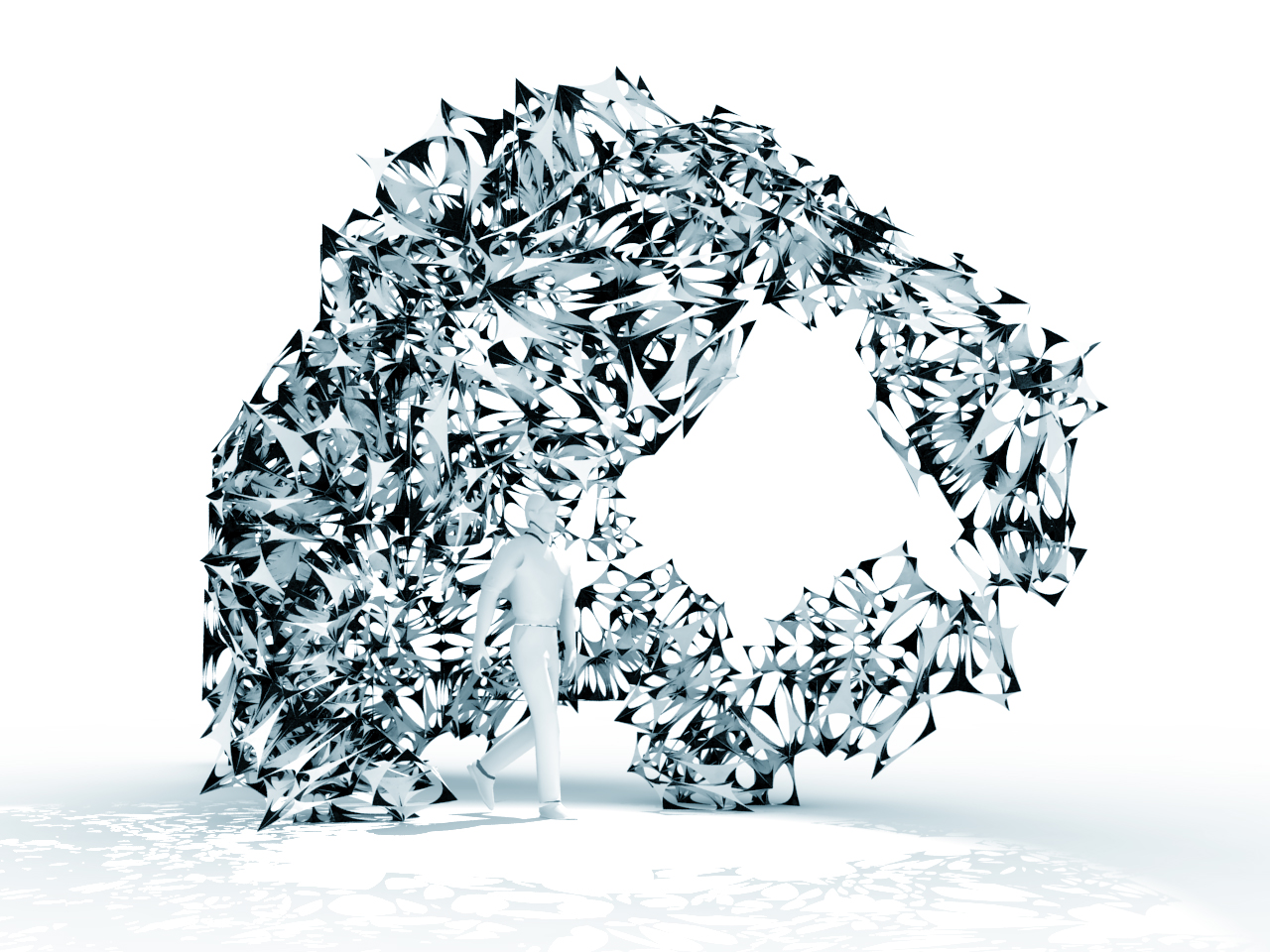
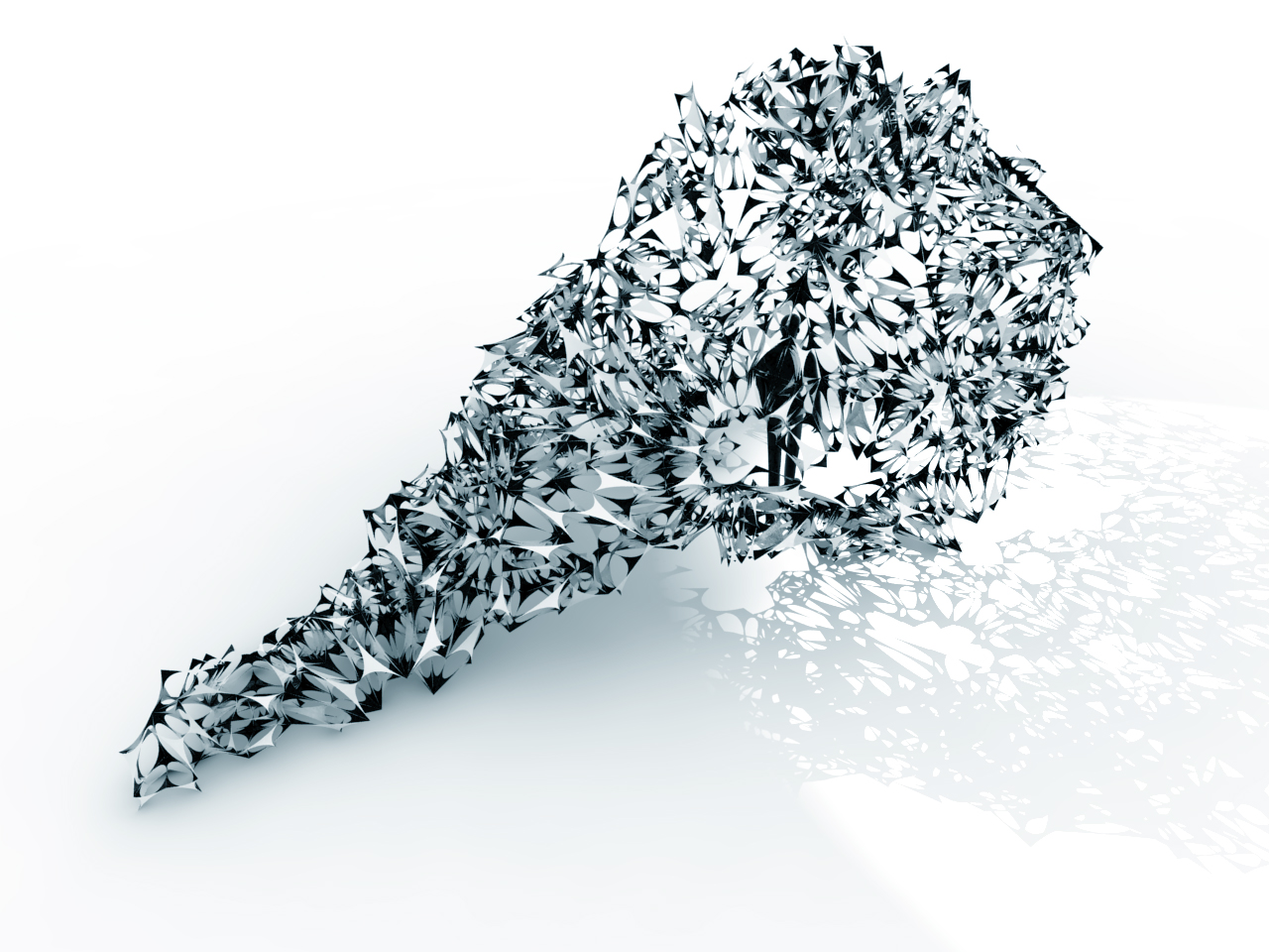
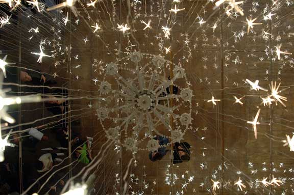
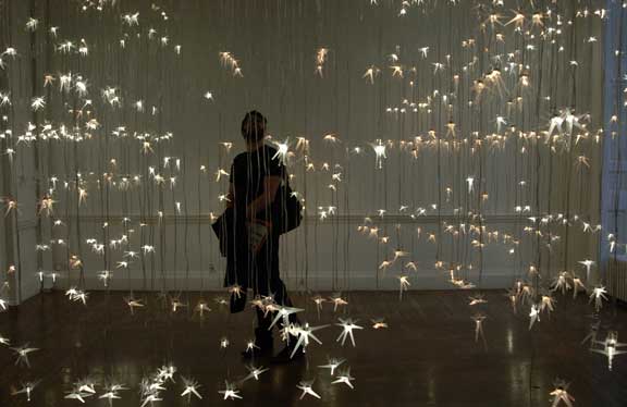
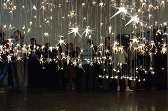
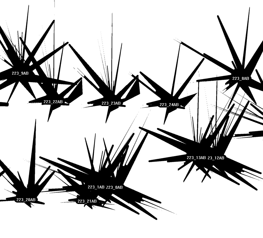
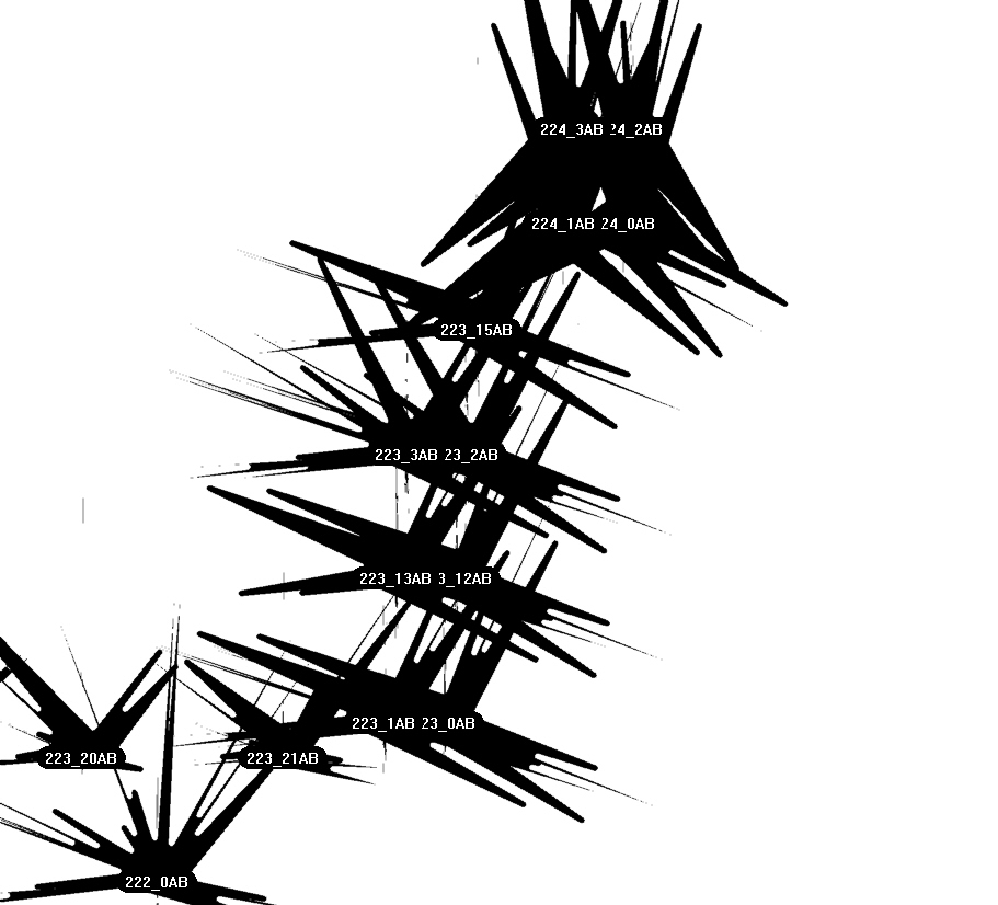
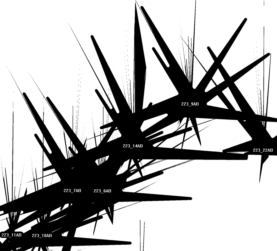
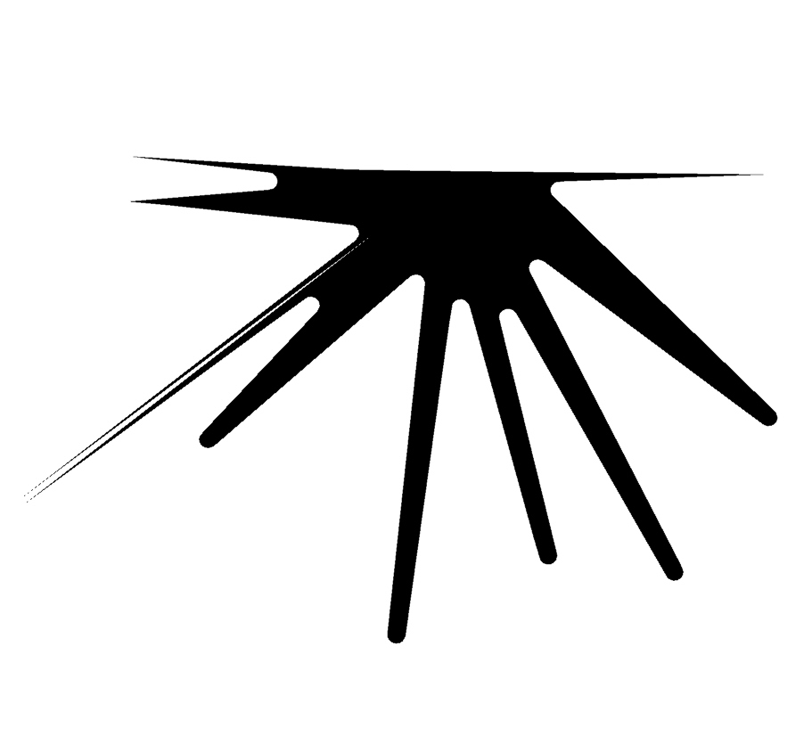
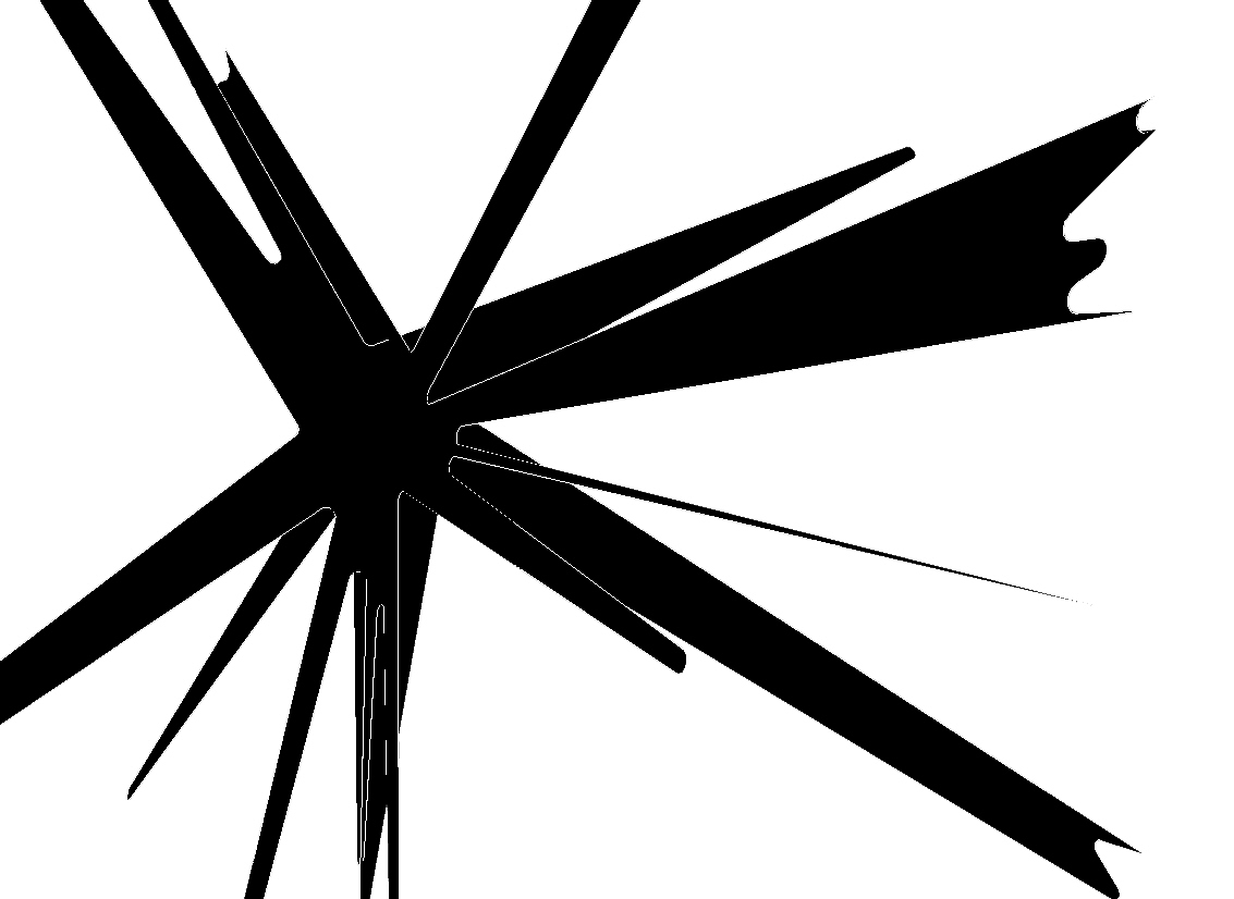
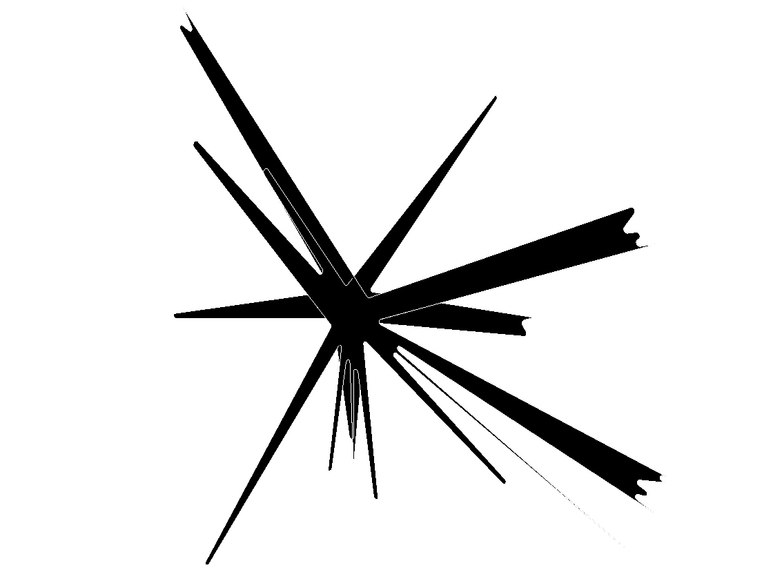
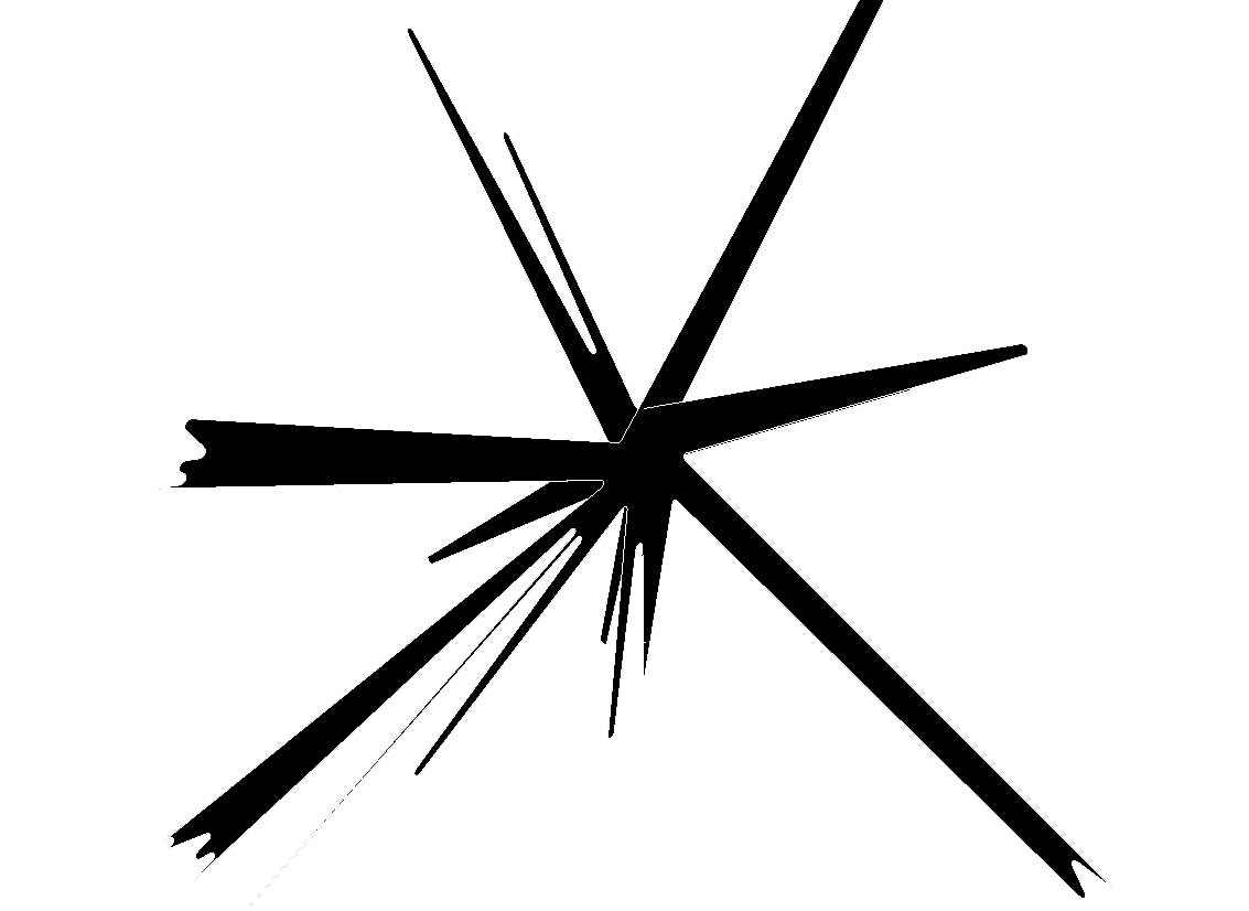
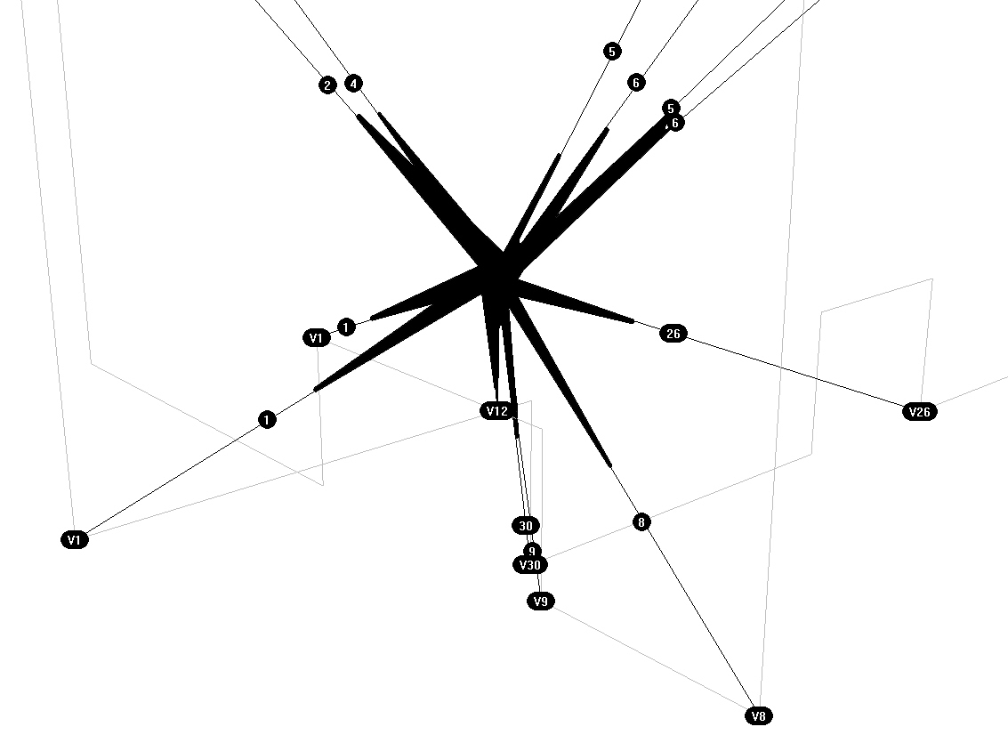
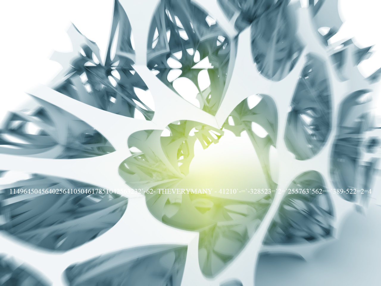
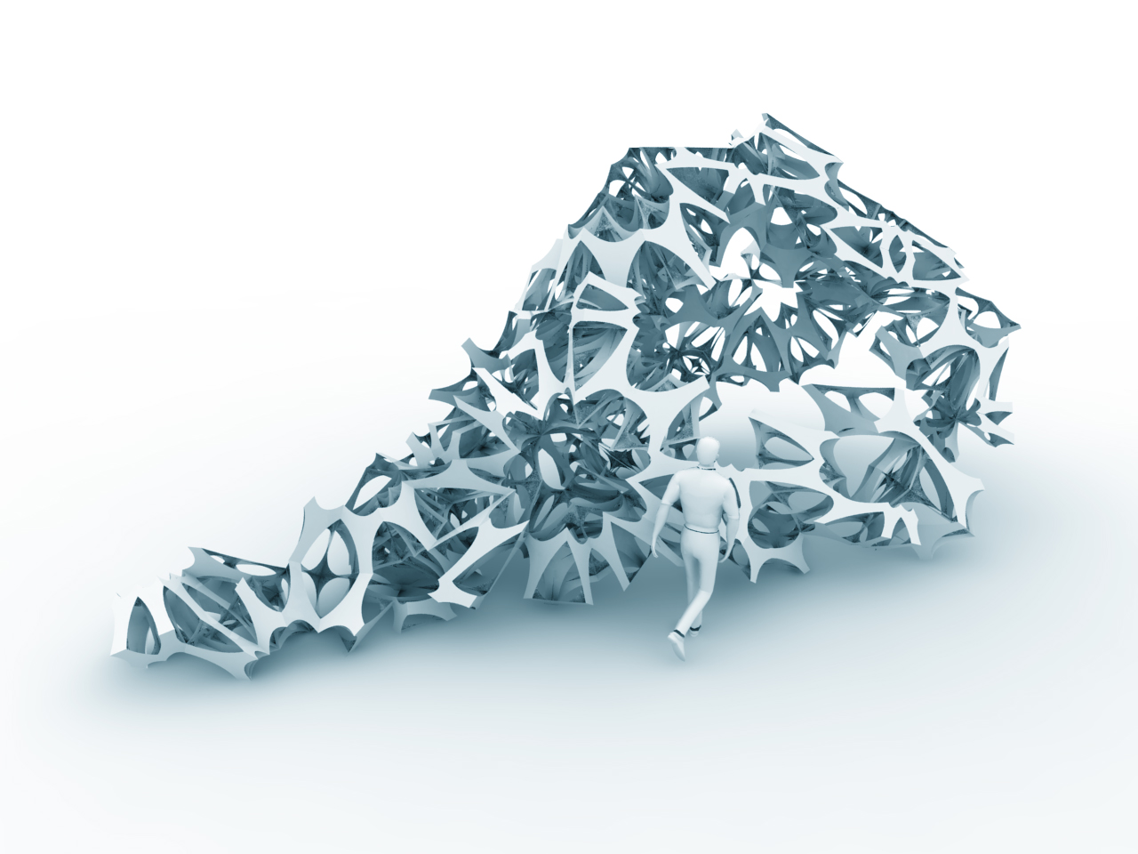
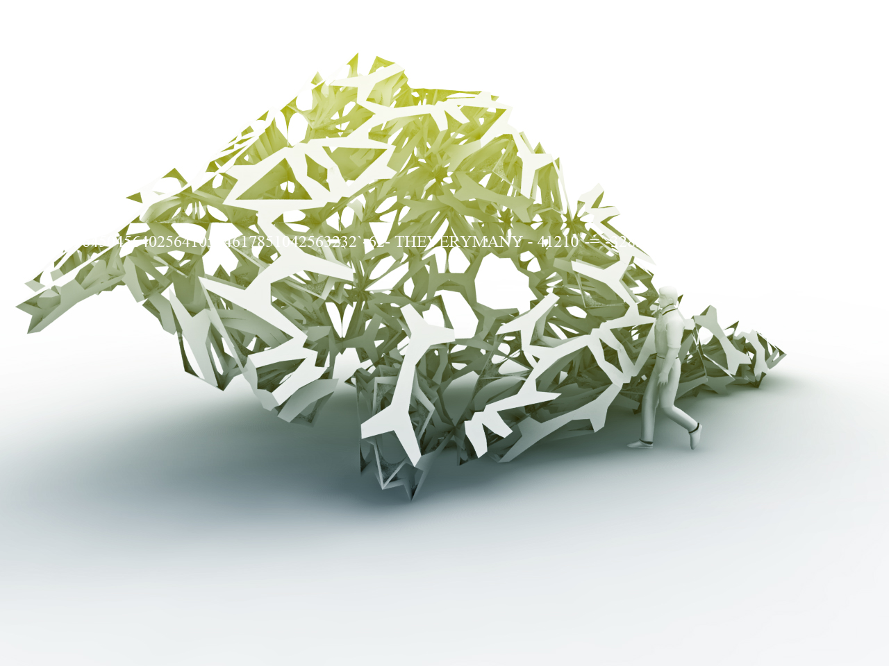
AA PAVILION "the powers of ten"
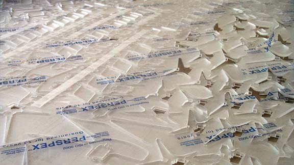
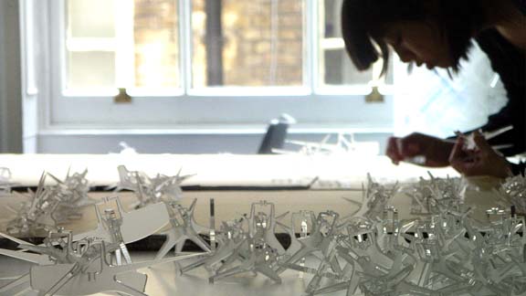
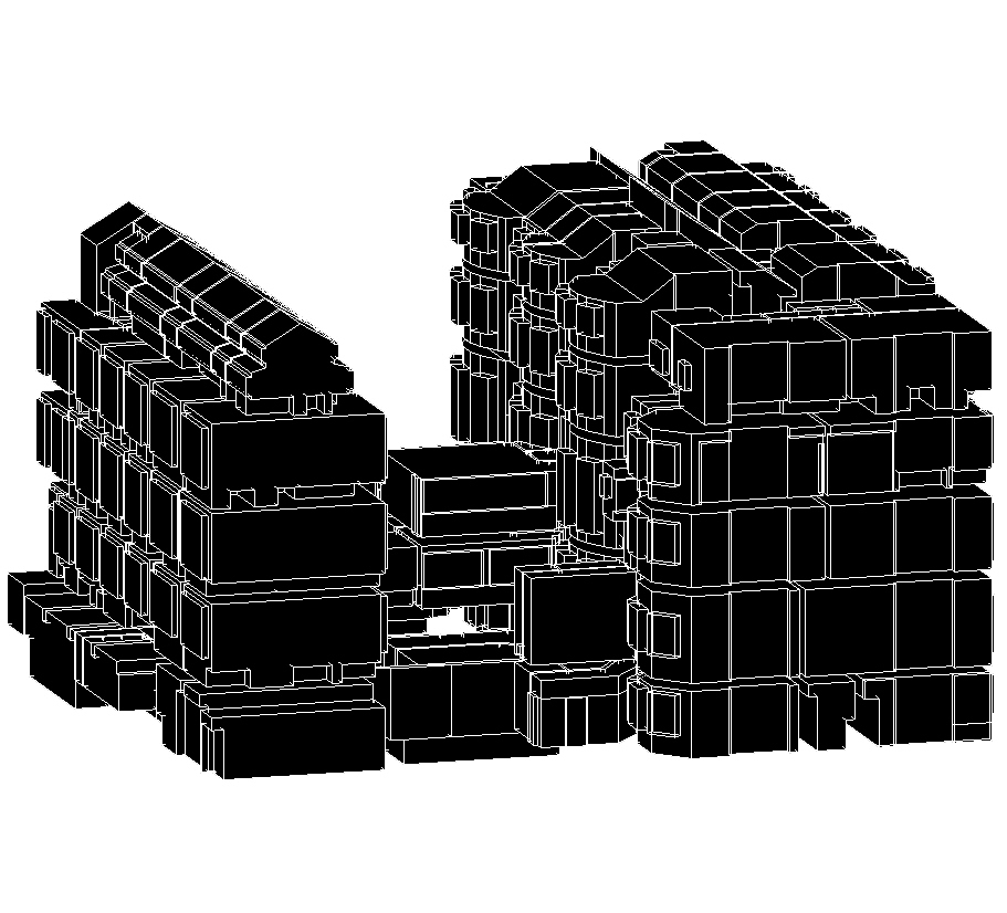
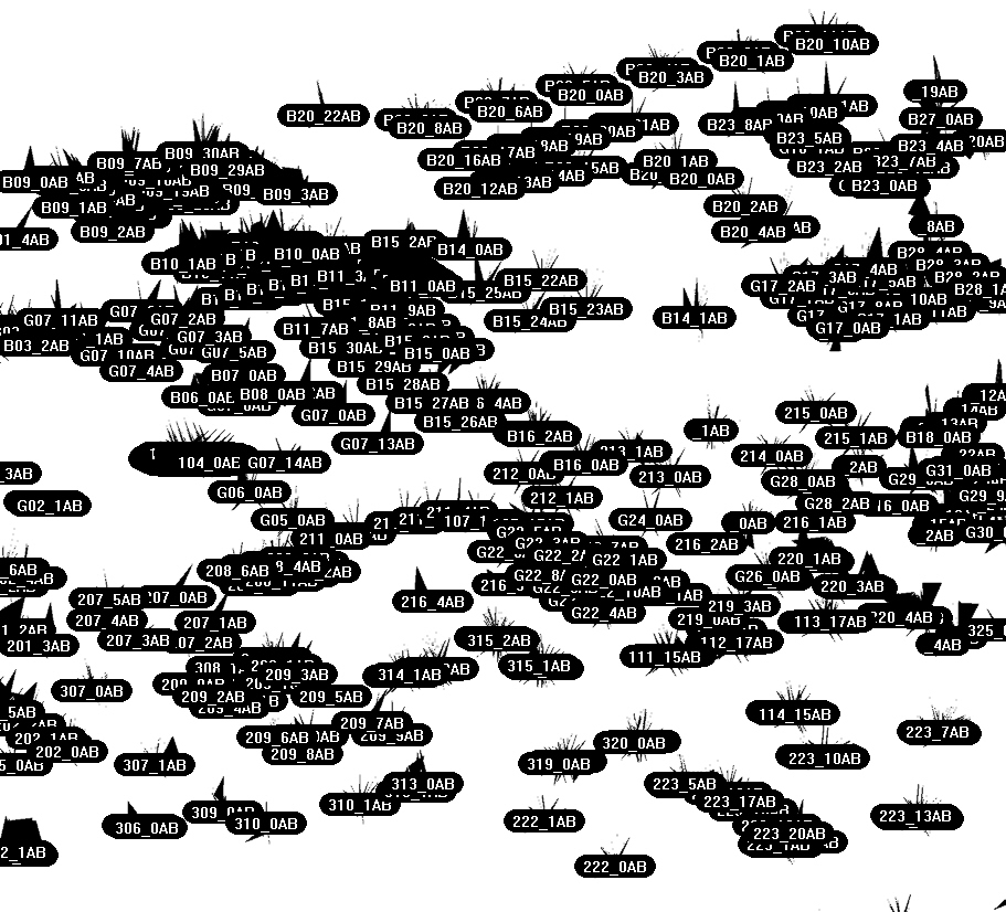
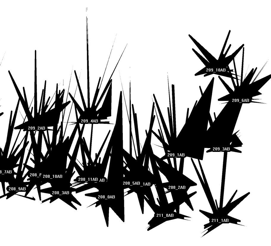
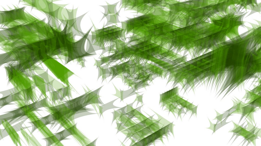
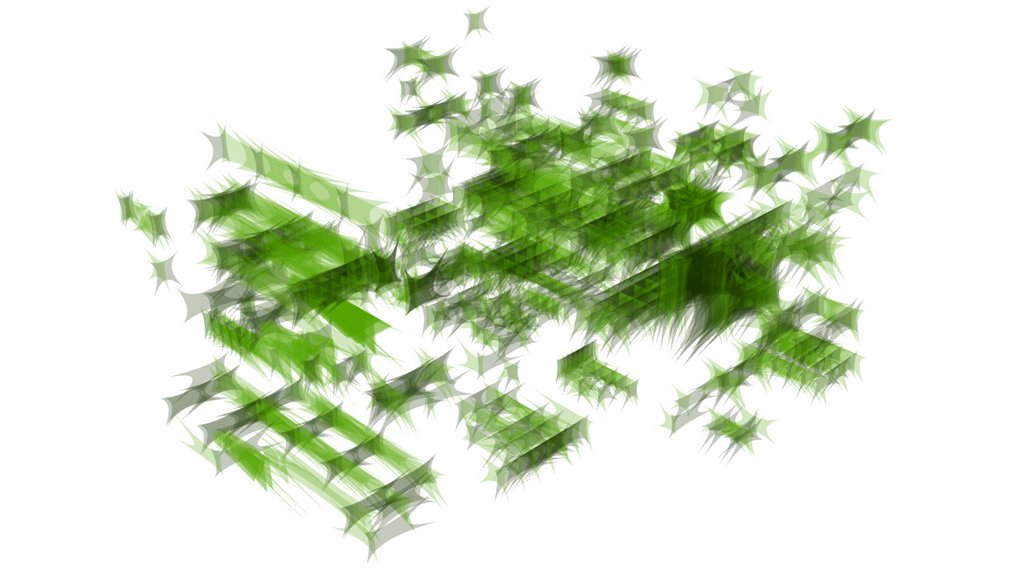
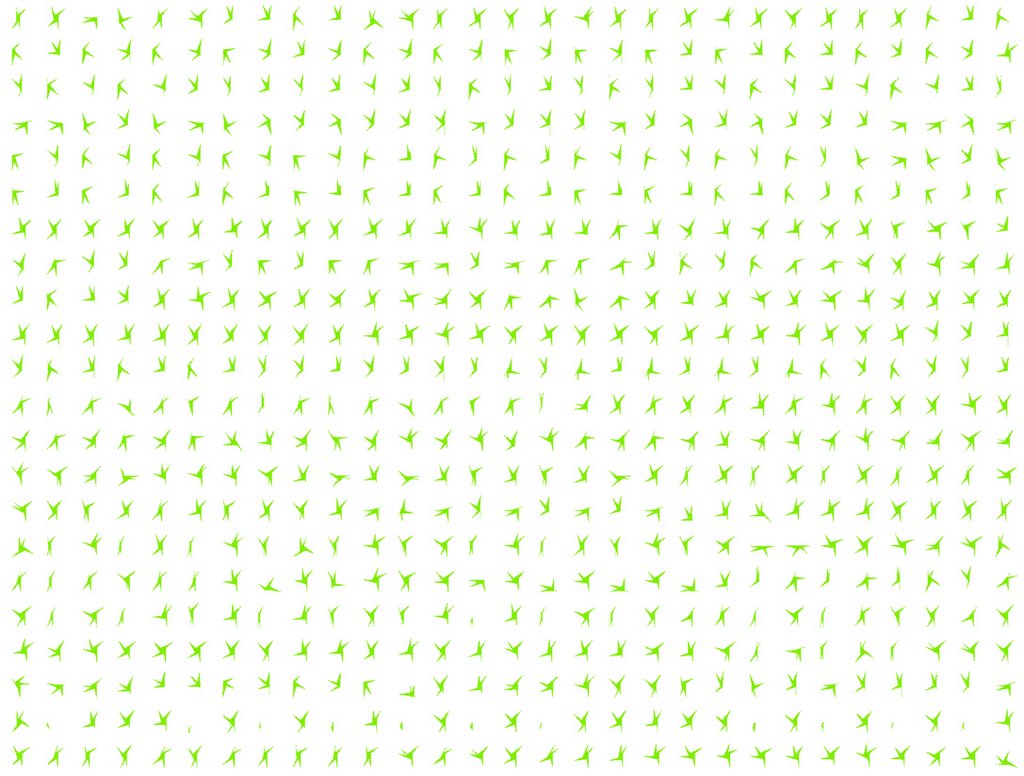
The different renders of that post are extracted from theverymany proposal for the AA Ten pavilion competition. The proposal was looking at "self-similarity" as the driving force behind the structure of its pavilion somehow allowing similarities within the possible "fractal" variation of the scale of its components -embeded within the logic of its aperiodic packing- and the emergent filiation between the 10 generations of AADRL graduates: all are different and all somehow within a certain depth are very similar...


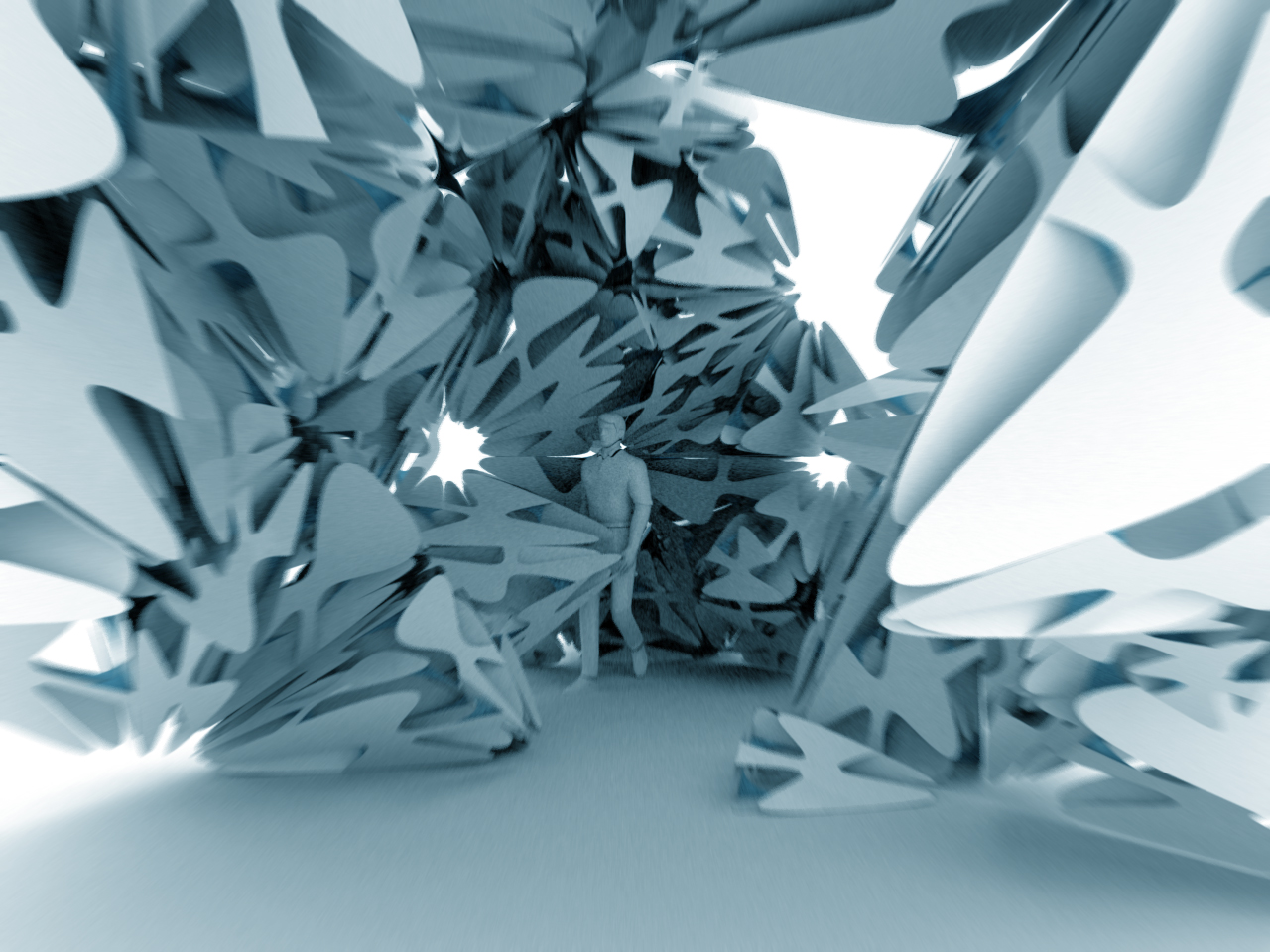
Theverymany is now developping further its proposal -currently pushing with its aperiodic series- and is looking for sponsors and eventual venues to construct it - anyone interested?...

Labels: , , , , ,

Friday, April 27, 2007

070427_LightHive_Update(3)


LightHive - the installation of Alex Haw at the AA - is open... (i.e. www.aalog.net)
Marc Fornes will be in London to follow Alex lecture on thursday May 3rd at the AA.


- all photos are from www.aalog.net -

Labels: , , ,

Friday, March 23, 2007

070322_LightHive_Update(3)


"the AA autrement"... is a set of abstracts rendered while figuring out the explicit and encoded rules set for LightHive "diffuseur grammaire": one could argue that each drawing is acting as some sort of map of the AA school, where the representation devices are a set of unique geomtries -carefully labelled- showing directions of obstacles, accidents and other folds within the terrain of every room...

Simplified as sets of closed polysurfaces, the 3D model allows the code to check for every room which light sources -selected as a point cloud- are enclosed within...


One of many shape... each arrows is growing along the direction of a vector pointing toward any corner of the room boundaries, or furniture piece...

Labels: , , , ,

Tuesday, March 20, 2007

070320_LIGHTHIVE_inProgress


Latest "abstracts" from the development of "LIGHTHIVE"

Lighthive is Alex Haw (Atmos) interactive exhibition at the AA, London (opening early May) for which Marc Fornes & theverymany have been invited to collaborate and write an explicit generative process abble to automatate the shape grammair of most of the 1500 components required to map the exisitng light condition within the AA building.

Each of those "3D star" component is an assembly of two 2D star which can be unrolled and laser cut flat onto thick sheet of acrylic.

INPUT (rhinoscript)
-get the 3D model of the AA school as a set of closed polysurface (each polysurface is one room including the boolean of the furnitures)
-get all the light source modelled at their scaled position as a point (color according to light type)

PSEUDO CODE: at the scale of the phenotype, here the 3D model of the school:
- for every pt (lightsource) do
- if pt is within closed polysurface do
- create two planes through each light (orthogonal to each other)
- for each plane do
- intersect plane and polysurface
- for each intersection curve do
- if pt is within curve do


COMPONENT: at the scale of the component "genotype", the challenge is to allow replication, proliferation while developping fondamentales genetic modifications such as custom amount of "spikes", each of those "spikes" having custom lenght, some "spikes" being able to bundle according to neighbourhood condition, etc, etc...

Those components are not displaying any swarm behaviour or collective intelligence, neither is based on dynamic feedback... BUT the generation of each "spike" is following a so long list of rules (possible target tests, few distance tests, many angle tests, etc, etc...) and possible branching transformations according to which there are able to develope and mutate... sometimes up to the point of displaying extreme behaviours impossible to expect... once more "very many" allows or describe a blurry boundary between "automatisation" and Emergence... between Repetition and Intelligence? blurry...

Labels: , , ,

Wednesday, February 14, 2007

Rh4_070214_LightHive_inProgress...


marc fornes & theverymany have been invited by Alex Haw (from Atmos and AA Ddiploma Master Unit 13) to collaborate to "LightHive : luminous architectural surveillance", an installation for the Architectural Association, London, April 2007.

EXPLICIT PROTOCOL v1.0: for every room of the 3d model of Architectural Association Building (including symbolic furniture) create Longitudinal and transversal section through the location of each light source, generate from the intersection boundaries a LED diffuser shape (each as a set of two planar shapes intersecting at 90 degrees), anotate the components and finally unfold them (to be laser-cut into flat acrylic sheets)...
According to the amount of components (more than 1400!), the challenge of that project is to build up the rhino engine code as light as possible in order to be abble to run it in one go! the entire descriptive process is yet taking 25 seconds to generate around 1200 components...
In progress...


BOUNDARY REPRESENTATION / BREPS (ie Wikipedia)

In computer-aided design, boundary representation—often abbreviated as B-rep or BREP—is a method for representing shapes using the limits. A solid is represented as a collection of connected surface elements, the boundary between solid and non-solid. The basic method was developed independently in the early 1970s by Braid in Cambridge (for CAD) and Baumgart in America (for computer vision). Braid continued his work with the research solid modeller BUILD which was the forerunner of many research and commercial solid modelling systems. Braid worked on the commercial systems ROMULUS, the forerunner of Parasolid, and on ACIS. Parasolid and ACIS are the basis for many of today's commercial CAD systems.

Boundary representation models are comprised of two parts: topology and geometry. The main topological items are: faces, edges and vertices. A face is a bounded portion of a surface; an edge is a bounded piece of a curve and a vertex lies at a point. Other elements are the shell (a set of connected faces), the loop (a circuit of edges bounding a face) and loop-edge links (also known as winged-edge links or half-edges) which are used to create the edge circuits.

Unlike the constructive solid geometry (CSG) representation, which represents objects as a collection of primitive objects and Boolean operations to combine them, boundary representation is more flexible and has a much richer operation set. This richer operation set makes boundary representation a more appropriate choice for CAD systems than CSG. CSG was used initially by several commercial systems because it was easier to implement but the advent of reliable commercial B-rep kernel systems like Parasolid and ACIS, mentioned above, has led to widespread adoption of B-rep for CAD. As well as the Boolean operations, B-rep has extrusion, chamfering, blending, drafting, shelling, tweaking and other operations which make use of these.

Boundary representation is essentially a local representation connecting faces, edges and vertices. An extension of this was to group sub-elements of the shape into logical units called "features". Pioneering work was done on this by Kyprianou in Cambridge using the BUILD system and continued and extended by Jared and others. Much other work on this topic has been done in several research centres throughout the world and it is a subject of continuing interest. Features, or geometric features, are the basis of many other developments, allowing high-level "geometric reasoning" about shape for comparison, process-planning, manufacturing, etc.

Boundary representation has also been extended to allow special, non-solid model types called non-manifold models. As described by Braid, normal solids found in nature have the property that, at every point on the boundary, a small enough sphere around the point is divided into two pieces, one inside and one outside the object. Non-manifold models break this rule. An important sub-class of non-manifold models are sheet objects which are used to represent thin-plate objects and integrate surface modelling into a solid modelling environment.


1200 components flat, all similar but all different

Tips'n tricks: (part of code only)
' getBoundingBox
arrBoundingBox = Rhino.BoundingBox(arrPolySrfs(i))
dblPlaneHeight = rhino.distance(arrBoundingBox(0), arrBoundingBox(4))
dblPlaneLong = rhino.distance(arrBoundingBox(0), arrBoundingBox(1))
dblPlaneTrans = rhino.distance(arrBoundingBox(0), arrBoundingBox(3))
' cuttingPlane LONGITUDINAL
arrPlaneOriginLong = array(arrPt(0)-dblPlaneLong, arrPt(1), arrPt(2)-dblPlaneHeight)
arrPlaneLong = Rhino.MovePlane (Rhino.WorldZXPlane, arrPlaneOriginLong)
strPlaneSrfLong = Rhino.AddPlaneSurface (arrPlaneLong, 2*dblPlaneHeight, 2*dblPlaneLong)
' intersect
strCrvIntersect = Rhino.IntersectBreps (arrPolySrfs(i), strPlaneSrfLong)
strCrvIntersectJoin = Rhino.JoinCurves (strCrvIntersect, True)
Call Rhino.SimplifyCurve (strCrvIntersect)
arrVertices = Rhino.CurveEditPoints(strCrvIntersect)

Labels: , , , , ,